NIBCO Copper Pipe Fittings
Download the NIBCO Copper Pipe Fittings for Revit — built with clean parameters, real-world standards, and ready for seamless use in your projects.
NIBCO Copper Pipe Fittings
Download the NIBCO Copper Pipe Fittings for Revit — built with clean parameters, real-world standards, and ready for seamless use in your projects.

Our free collection of NIBCO pipe fittings makes it easier than ever to model copper piping systems accurately and efficiently in Revit.
This free collection of NIBCO copper pipework fittings makes it easier than ever to model copper piping systems accurately and efficiently in Revit.
Copper soldered pipework offers long-term durability, high heat tolerance, and excellent leak resistance, making it a trusted choice for residential, commercial, and HVAC systems. It can withstand high temperatures and pressure without degrading as it has no internal components such as gaskets.
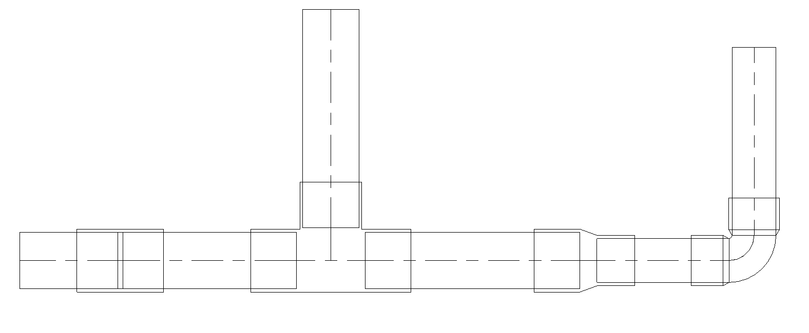
The collection features a small but powerful set of essential components – pipe type, reducer, coupling, bend (elbow), end cap, reducing and equal tee. We've created the pipe type itself with the full routing preferences already defined, so you can load it and start drawing your pipework without a second thought.
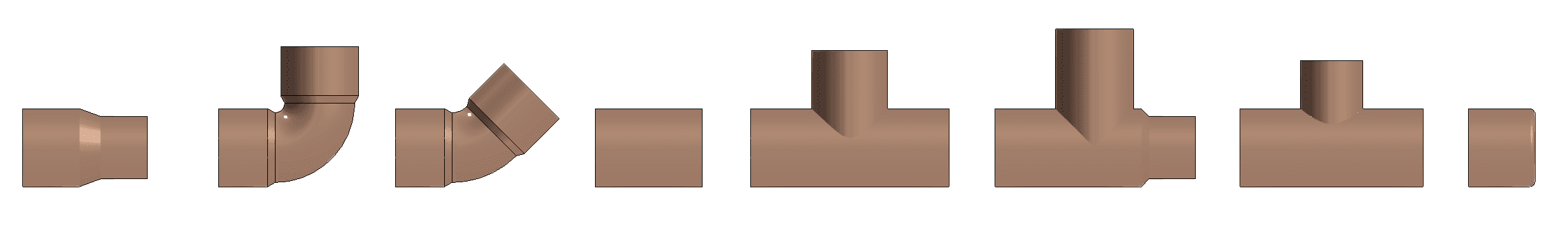
Each family is modeled to match NIBCO's product specifications and copper fitting standards, ensuring dimensional accuracy and peace of mind when coordinating. More about this later on in the post.
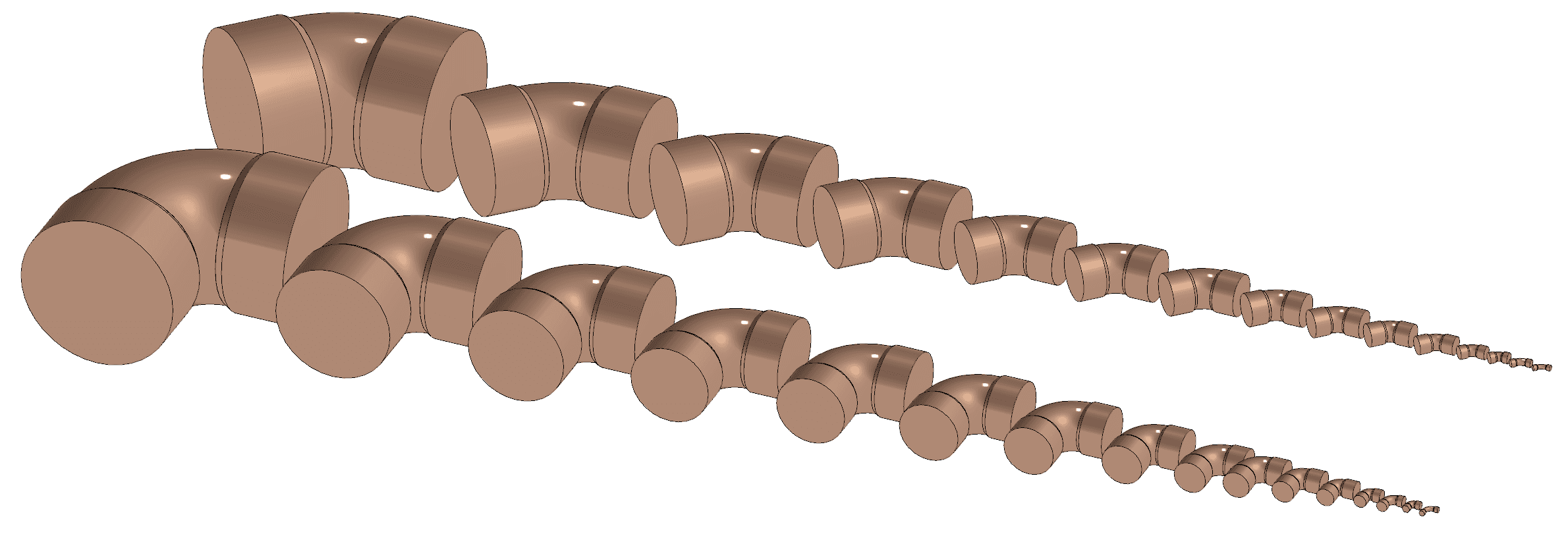
Bends
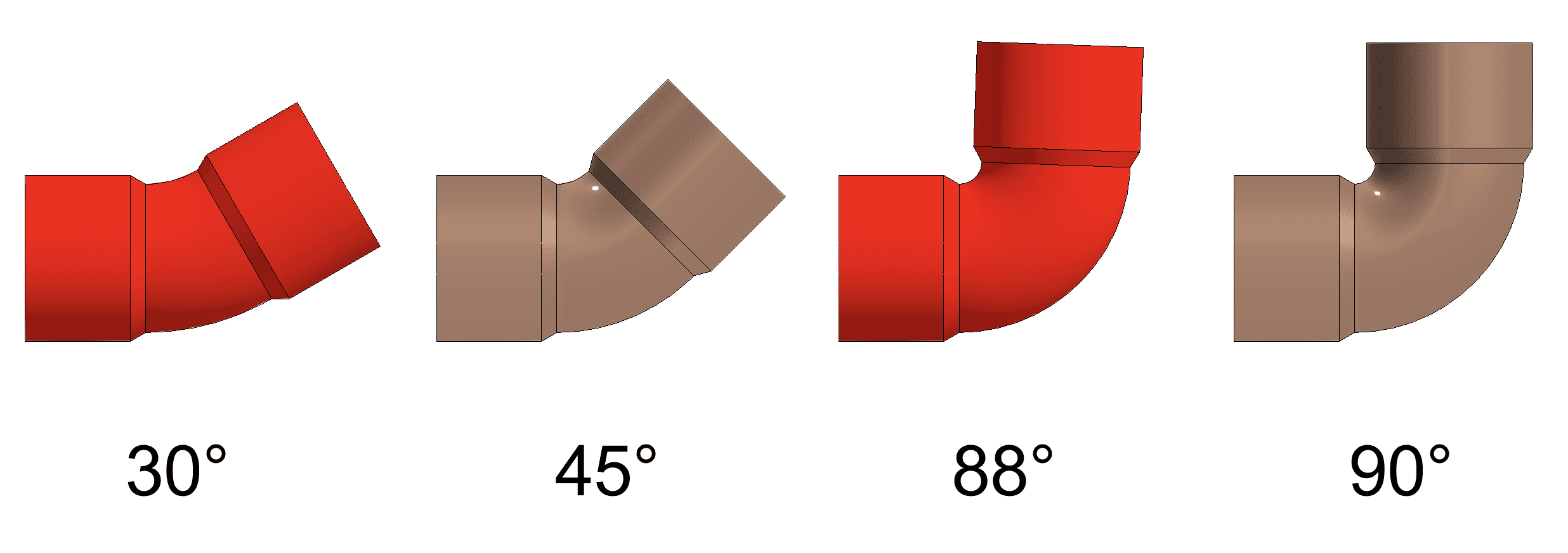
The bend covers NIBCO’s 45 degree and 90 degree close rough elbows ranging from 1/8” to 8” nominal diameters.
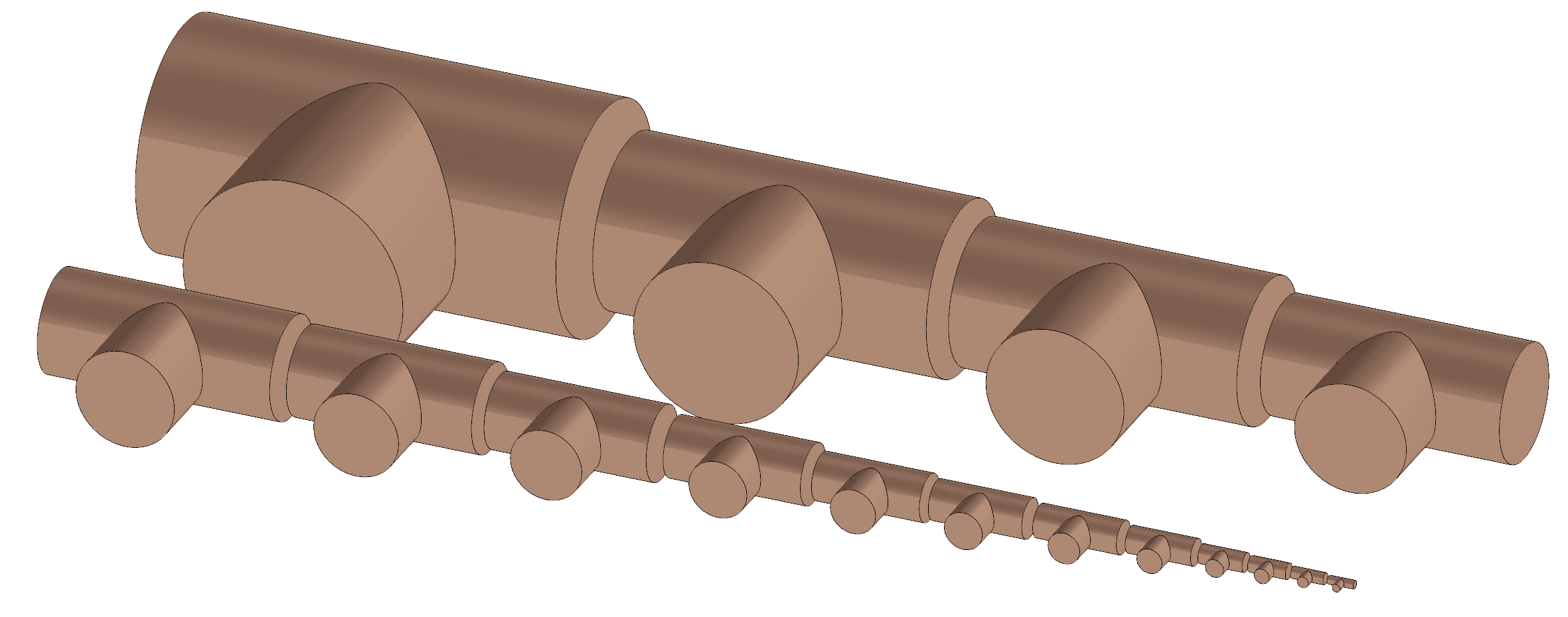
Tees
The tee family is capable of equal size connections, reducing branches and runs (or both where possible) ranging from 1/8” to 8” nominal diameters.
Flexible Installation
The pipe type has been given a 1 degree tolerance. For instance, the 90 degree bend can produce 89-91 degree bends to suit any small discrepancies in coordination. This tolerance also allows for installation at fall/gradient without throwing out a Revit error which can happen with some ‘out of the box’ fittings.
IsCustom Option
Our NIBCO soldered copper pipe fittings take advantage of Revit’s IsCustom option for pipe fittings. The IsCustom option allows the Revit user to create piping systems with a more fluid workflow.
Whenever there is an incorrect value for angle or nominal diameter (depending on the fitting), Revit will allow the pipe to be drawn but will flag that it's using a custom fitting and will color the fitting bright red.
This allows you to quickly and efficiently draw your system, while having an easy and unobtrusive way to spot and fix potential issues.
One Last Thing: Choosing the Connector Position
One final thing to note is the connector position for these families. We’ve been creating pipe fitting Revit families for many years now, including the AWWA Autodesk pipe fittings.
Typically, the connectors are placed at the ends of the fittings. While this may be easier for Revit (or at least it was thought to be years ago), it does mean that a material takeoff will be inaccurate.
For example, 1” ND copper pipework is incredibly common and the fittings have a socket depth of nearly 1 inch. This means you miss 2 inches of required pipe length for every fitting used. Even a small office building will use up to 300 1” ND fittings, equating to approximately 50 feet of pipework not accounted for in a Revit material takeoff.
In a world where BIM is meant to be the default, we should aim to be more accurate and efficient than that.
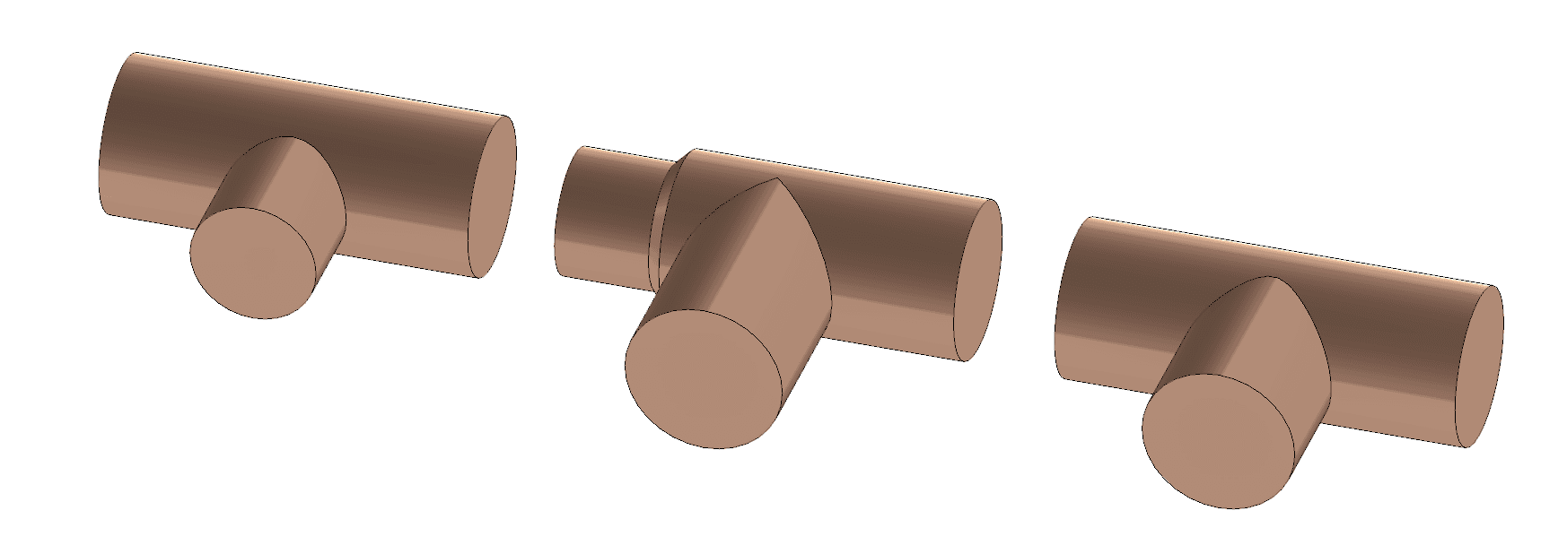
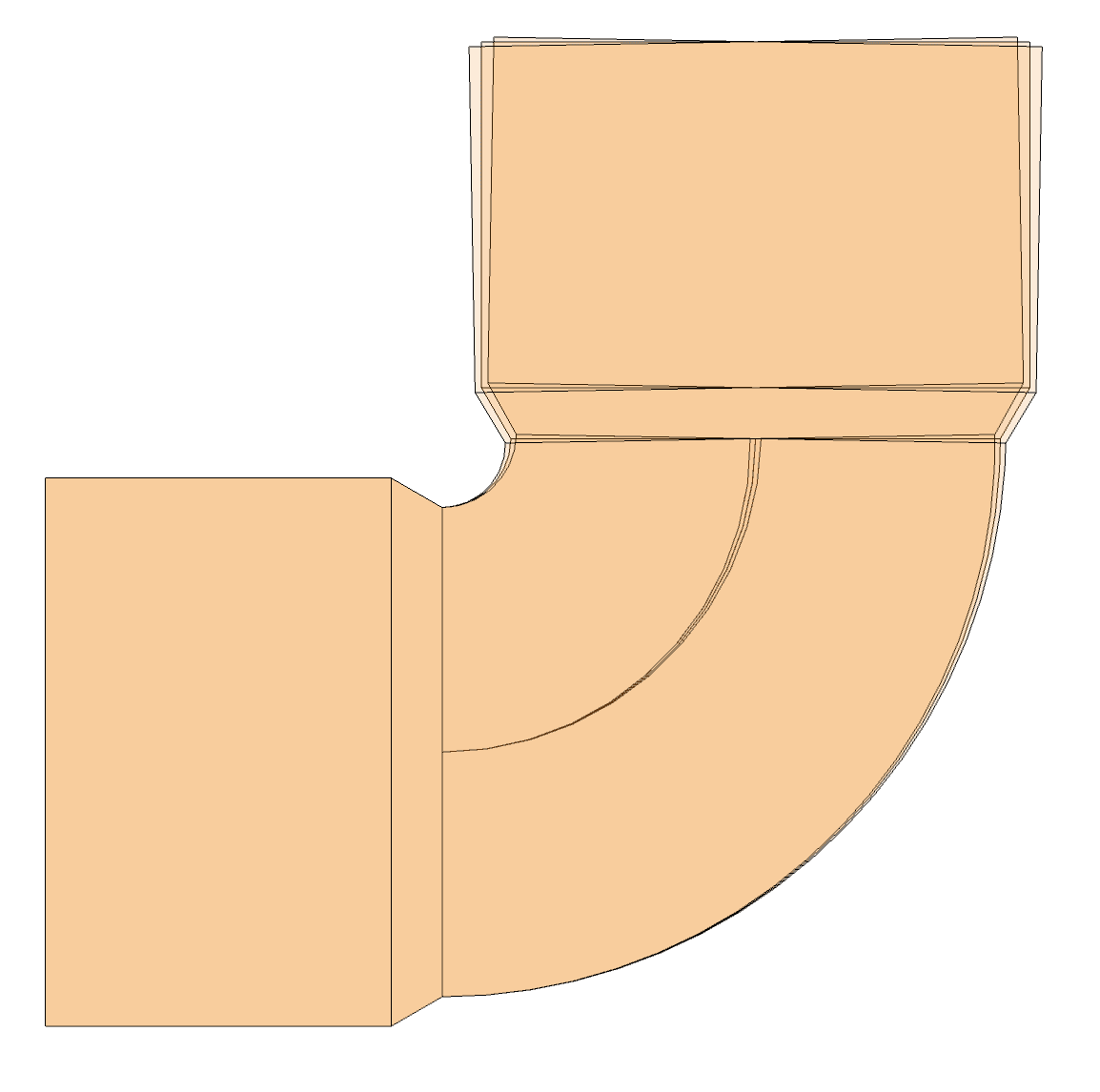
That’s why these Revit families have their connectors placed inside the fitting as per real life installation. The image below shows how the pipe ends connect inside of the sockets for accurate coordination and material takeoffs.
Collection Content List
Pipe Type - NIBCO
Bend
Reducer
Coupling
Combined Equal and Reducing Tee
Cap End
Our free collection of NIBCO pipe fittings makes it easier than ever to model copper piping systems accurately and efficiently in Revit.
This free collection of NIBCO copper pipework fittings makes it easier than ever to model copper piping systems accurately and efficiently in Revit.
Copper soldered pipework offers long-term durability, high heat tolerance, and excellent leak resistance, making it a trusted choice for residential, commercial, and HVAC systems. It can withstand high temperatures and pressure without degrading as it has no internal components such as gaskets.
The collection features a small but powerful set of essential components – pipe type, reducer, coupling, bend (elbow), end cap, reducing and equal tee. We've created the pipe type itself with the full routing preferences already defined, so you can load it and start drawing your pipework without a second thought.
Each family is modeled to match NIBCO's product specifications and copper fitting standards, ensuring dimensional accuracy and peace of mind when coordinating. More about this later on in the post.
Bends
The bend covers NIBCO’s 45 degree and 90 degree close rough elbows ranging from 1/8” to 8” nominal diameters.
Tees
The tee family is capable of equal size connections, reducing branches and runs (or both where possible) ranging from 1/8” to 8” nominal diameters.
Flexible Installation
The pipe type has been given a 1 degree tolerance. For instance, the 90 degree bend can produce 89-91 degree bends to suit any small discrepancies in coordination. This tolerance also allows for installation at fall/gradient without throwing out a Revit error which can happen with some ‘out of the box’ fittings.
IsCustom Option
Our NIBCO soldered copper pipe fittings take advantage of Revit’s IsCustom option for pipe fittings. The IsCustom option allows the Revit user to create piping systems with a more fluid workflow.
Whenever there is an incorrect value for angle or nominal diameter (depending on the fitting), Revit will allow the pipe to be drawn but will flag that it's using a custom fitting and will color the fitting bright red.
This allows you to quickly and efficiently draw your system, while having an easy and unobtrusive way to spot and fix potential issues.
One Last Thing: Choosing the Connector Position
One final thing to note is the connector position for these families. We’ve been creating pipe fitting Revit families for many years now, including the AWWA Autodesk pipe fittings.
Typically, the connectors are placed at the ends of the fittings. While this may be easier for Revit (or at least it was thought to be years ago), it does mean that a material takeoff will be inaccurate.
For example, 1” ND copper pipework is incredibly common and the fittings have a socket depth of nearly 1 inch. This means you miss 2 inches of required pipe length for every fitting used. Even a small office building will use up to 300 1” ND fittings, equating to approximately 50 feet of pipework not accounted for in a Revit material takeoff.
In a world where BIM is meant to be the default, we should aim to be more accurate and efficient than that.
That’s why these Revit families have their connectors placed inside the fitting as per real life installation. The image below shows how the pipe ends connect inside of the sockets for accurate coordination and material takeoffs.
Collection Content List
Pipe Type - NIBCO
Bend
Reducer
Coupling
Combined Equal and Reducing Tee
Cap End


Kinship
The best way to manage Revit content
Kinship
The best way to manage Revit content
Kinship
The best way to manage Revit content
Similar Articles


Never miss an update with our monthly newsletter
Get the latest company news, product updates, blog posts and free Revit content from Kinship. Delivered directly to your inbox no more than once a month.
By submitting your email, you agree to receive newsletter emails.
Support
Never miss an update with our monthly newsletter
Get the latest company news, product updates, blog posts and free Revit content from Kinship. Delivered directly to your inbox no more than once a month.
By submitting your email, you agree to receive newsletter emails.
Support
Never miss an update with our monthly newsletter
Get the latest company news, product updates, blog posts and free Revit content from Kinship. Delivered directly to your inbox no more than once a month.
By submitting your email, you agree to receive newsletter emails.
Support