From 3D CAD to Native Revit Using Adaptive Families

Have you ever found yourself looking at the jagged, tessellated 3D CAD import of a chair in a Revit model and thought, "Hmm, that's a lot of polygons."
Then you populated your model with dozens of those chairs, and thought, "Hmmm, my model is very slow."
And then you spent a day building what ends up being a 3MB family with 8 swept blends and 11 voids that looks "kind-of-sort-of ok, just don't zoom in too much." You know the type.
Good news, there is a better way. Complex, smooth surfaces can actually be modelled relatively easily as a form in an adaptive family. This post introduces a workflow that lets you do just that in order to reproduce 3D CAD geometry natively in Revit.
We'll begin with a brief introduction to forms in Revit adaptive families. Then we'll go over how to identify and draw profiles that follow the imported geometry. Finally, there is a step-by-step guide, followed by few tips and side notes.
Sample Use Case
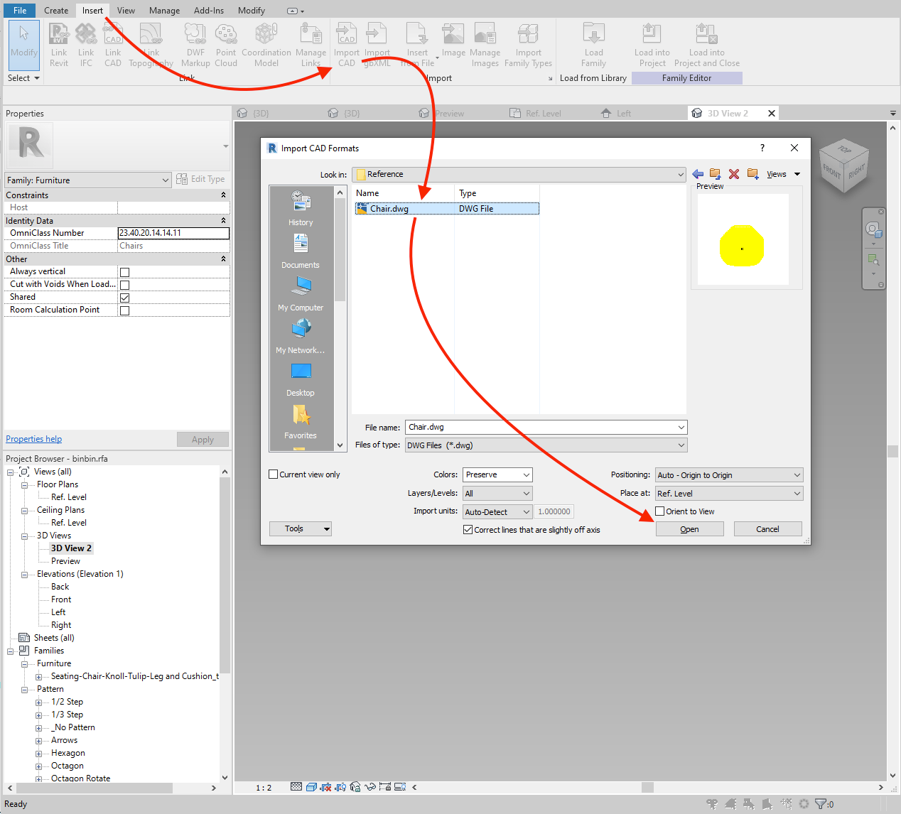
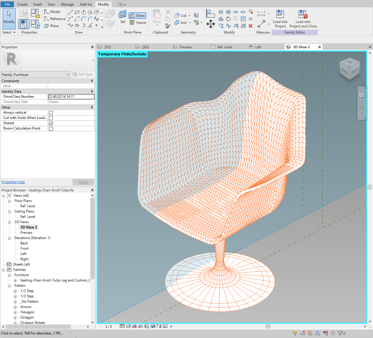
The shell of an injection-molded chair is the perfect application for this workflow. In the Revit family editor, we will import the 3D geometry in DWG format and use it as a reference for tracing profiles for the final shell.
If you ever wanted to "shrink wrap" something in Revit, you're in the right place.
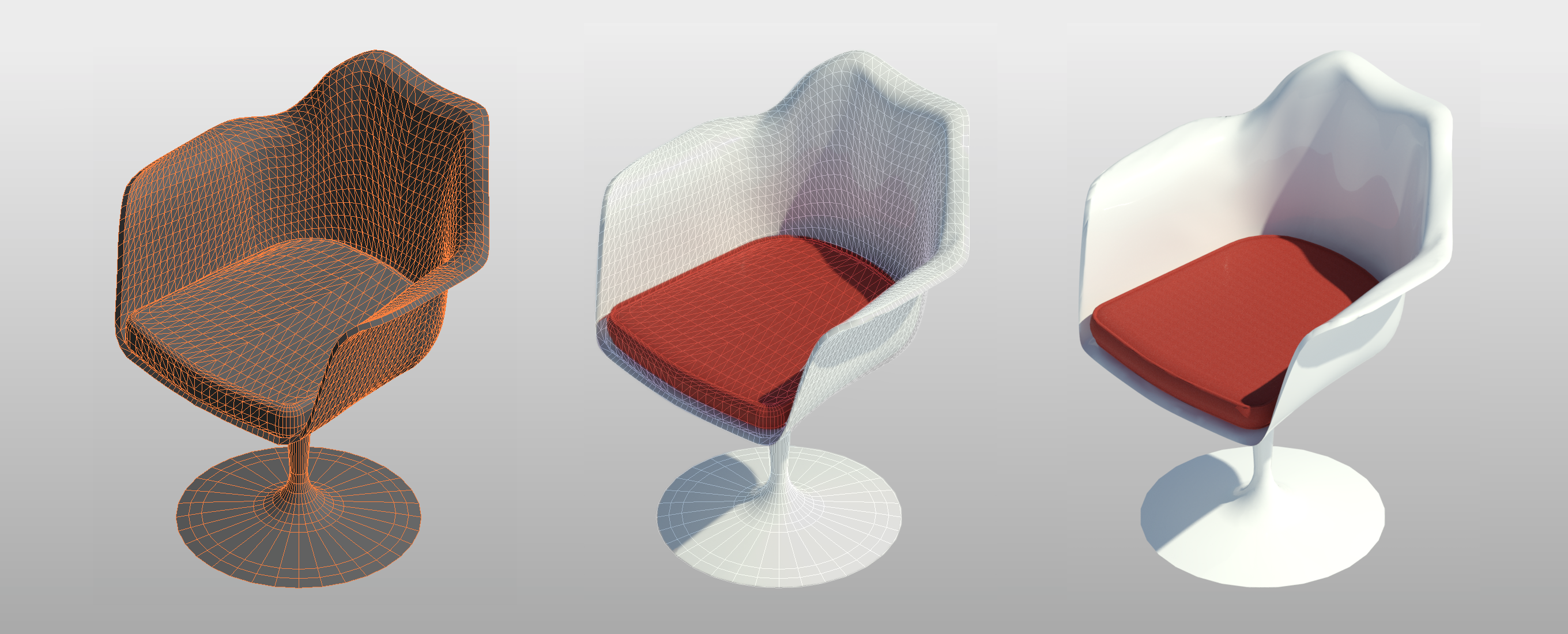
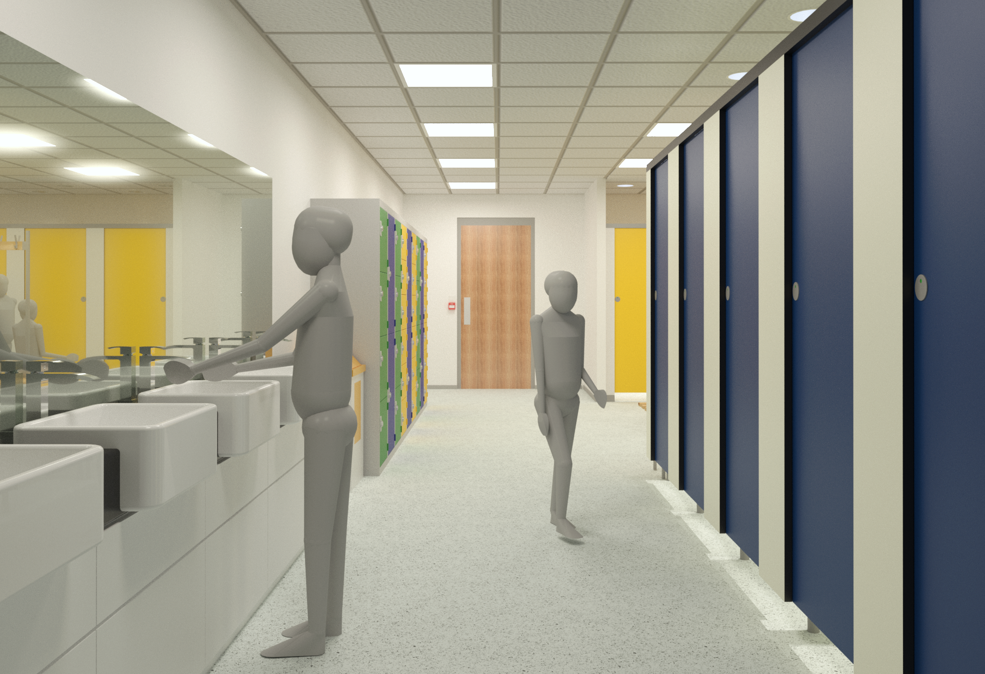
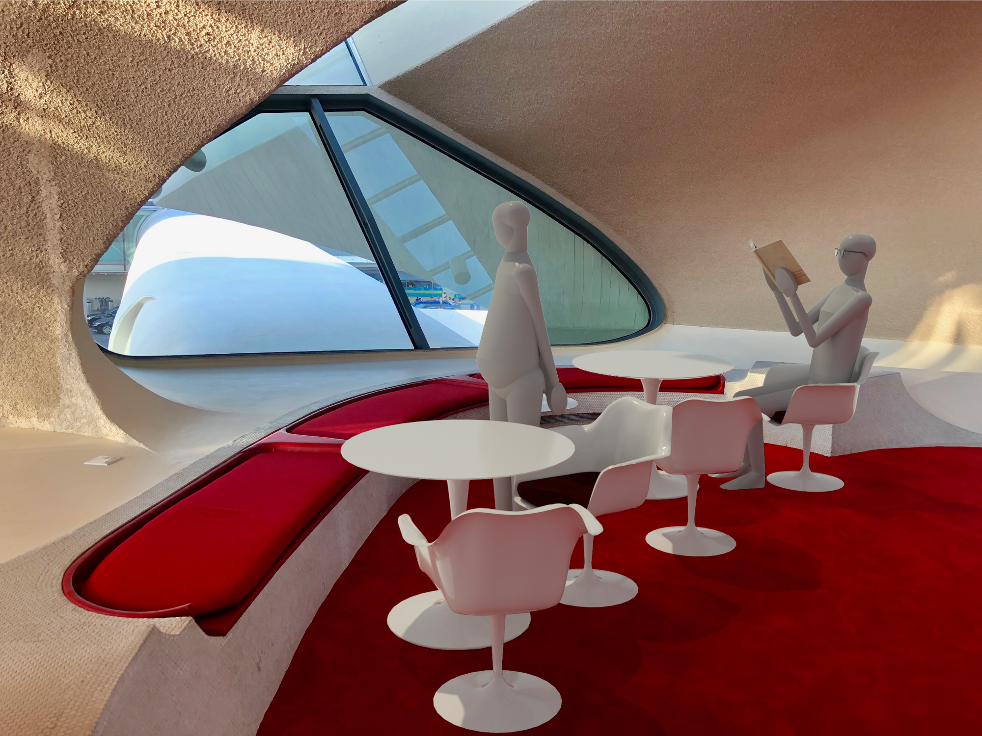
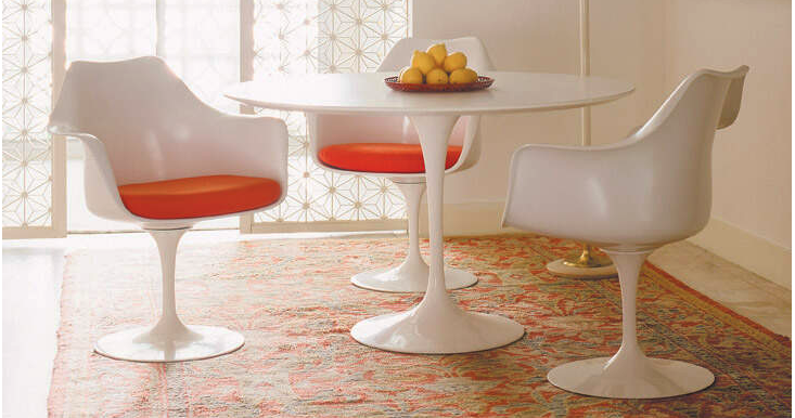
The shell for our sample use case comes from the Tulip armchair, by Eero Saarinen. The complete Revit family, with multiple finish options and accompanied by a matching table and Andy entourage family, will be available for download soon as part of our free content collections for iconic seating. If you're curious to see the final product, check back here or sign up for our monthly newsletter.
Forms
A form in Revit is simply a surface projected from one line or stretched across two or more lines. Both reference lines and model lines can be used.
In the screenshots below, I started a new family using the Generic Model Adaptive template. Then I drew two splines and created a form.
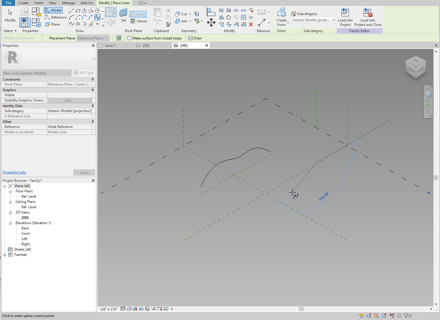
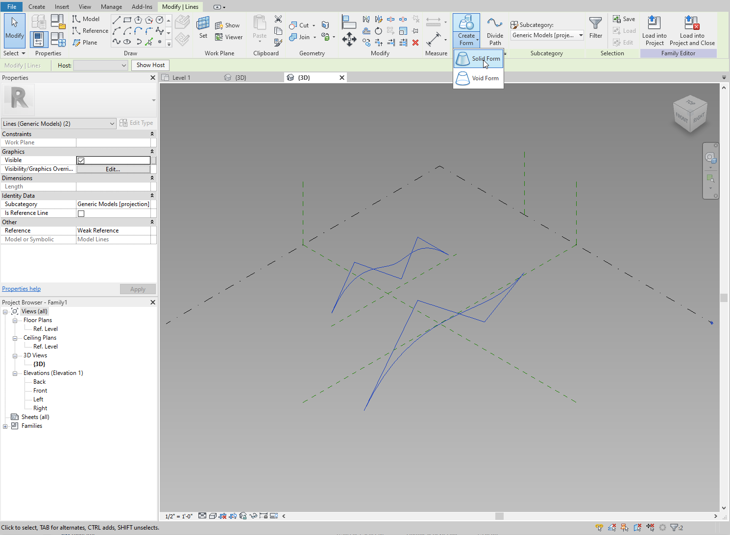
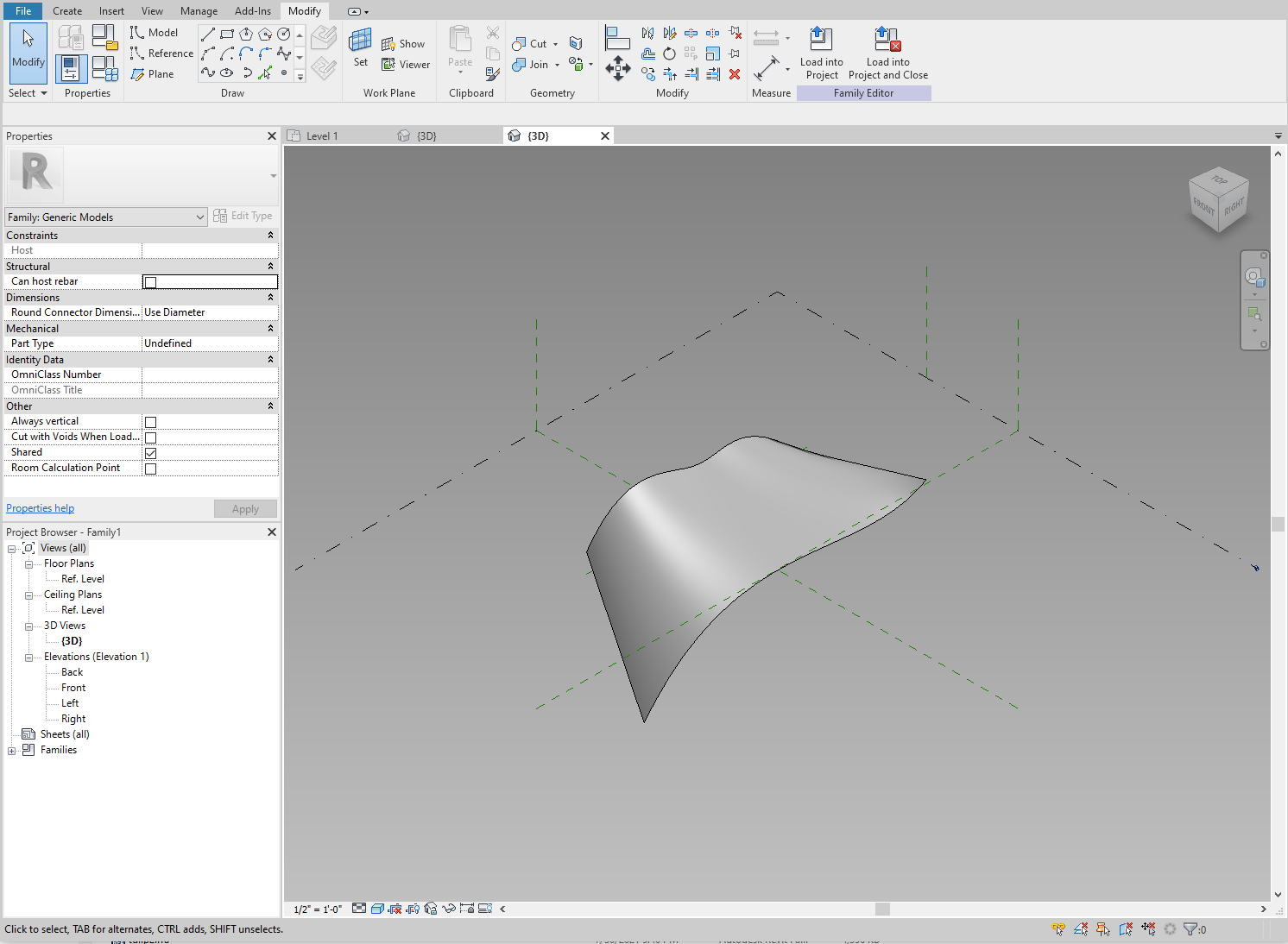
The lines used to create the form become profiles for the new surface. To achieve more complex shapes, we can use multiple profiles to create a single form.
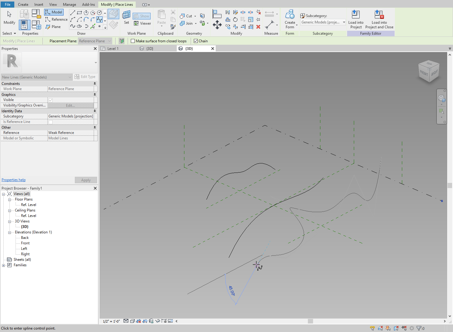
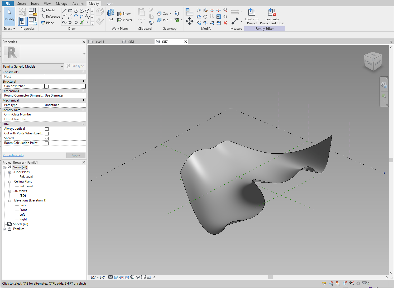
Let's delete the form, add a third more radical profile, then select all three lines and create a new form.
Profiles
By creating multiple profiles, we can create any (within reason) smooth, continuous surface in Revit. This is how we are going to create the shell for our chair.
Typically this would be quite a task. Figuring out the profile at each section by eye is tricky to say the least. In our case, however, we have a 3d CAD model that we can use as a reference.
So how do we get usable sections where we can identify the profiles? Revit's section views won't be of any help – CAD imports are not cuttable, so even the most shallow section is still going to display the entire geometry. Slicing the 3D into profiles in CAD is also out of the question.
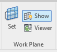
If you've ever questioned the usefulness of being able to display the active work plane in Revit, now is when this button will earn its place on the ribbon.
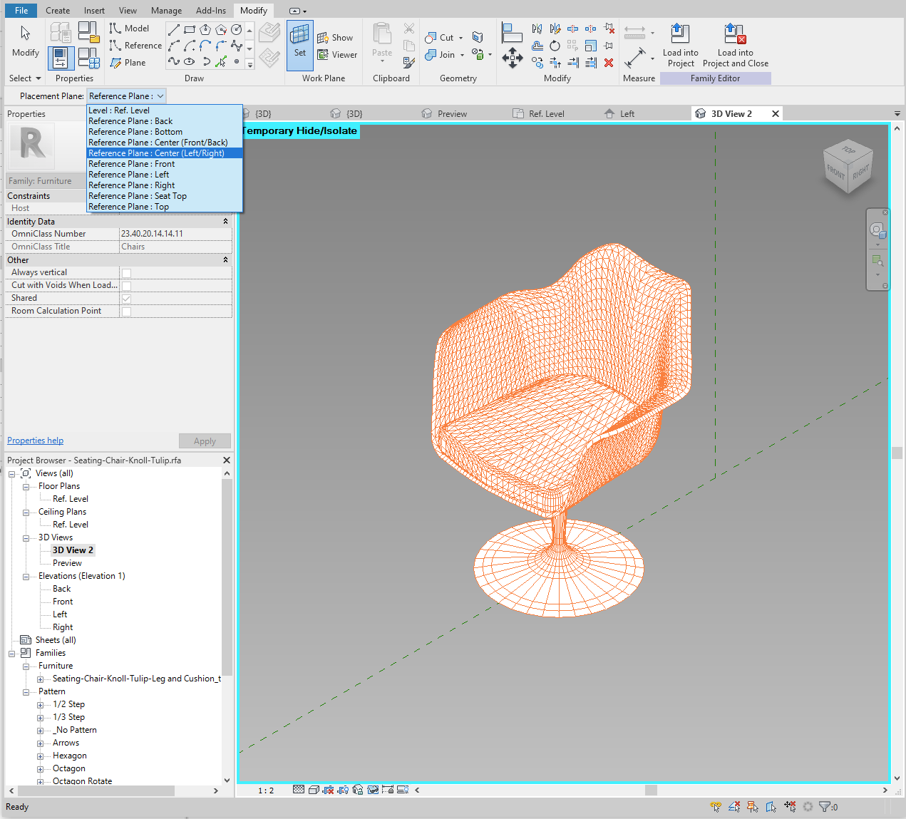
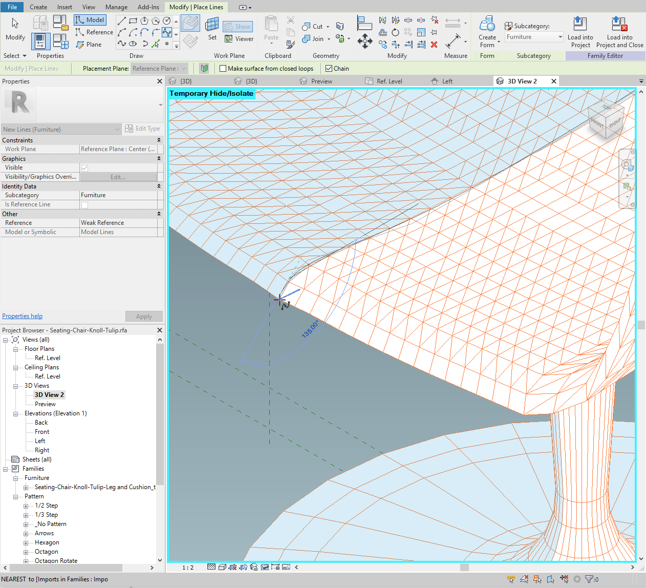
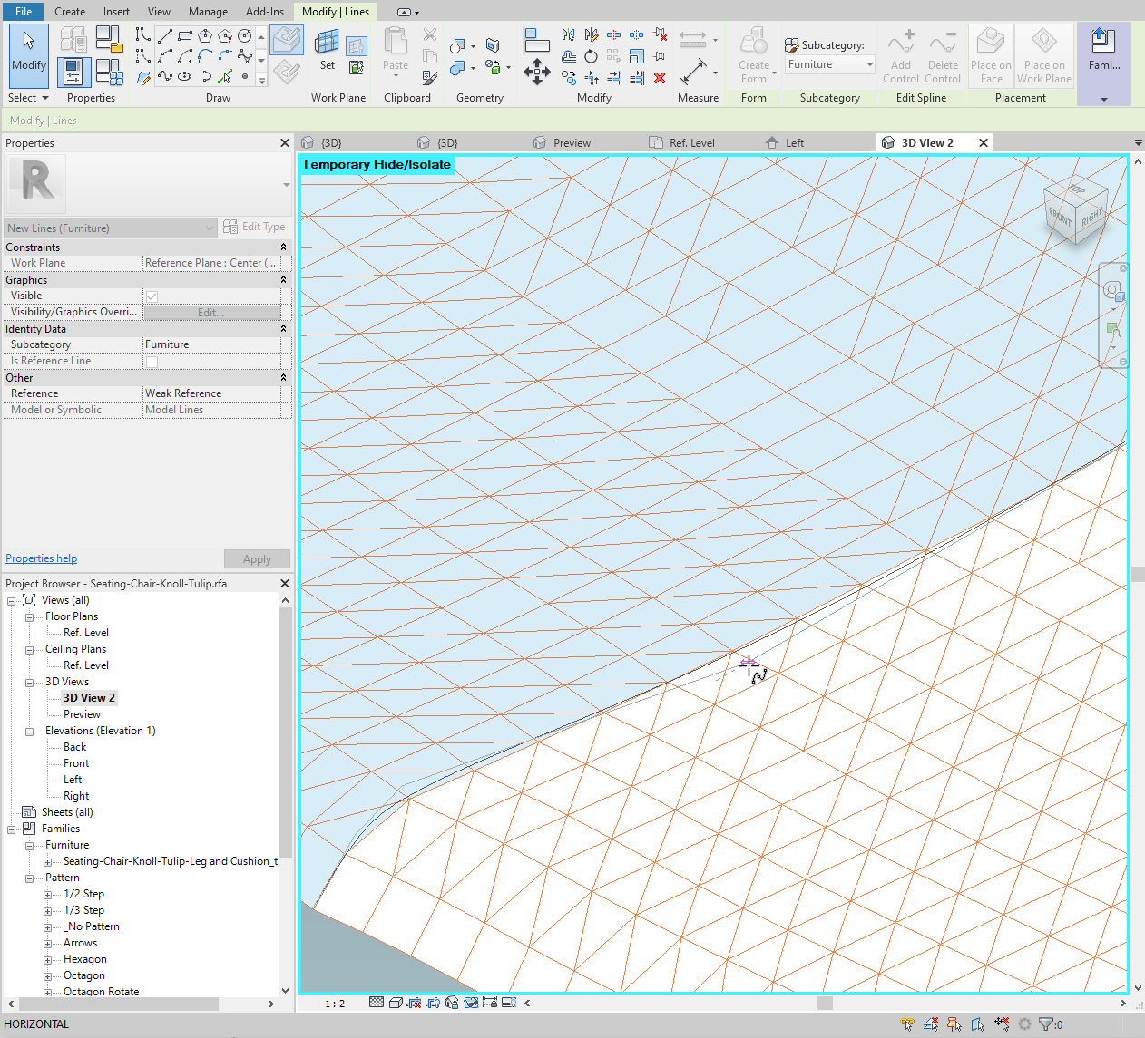
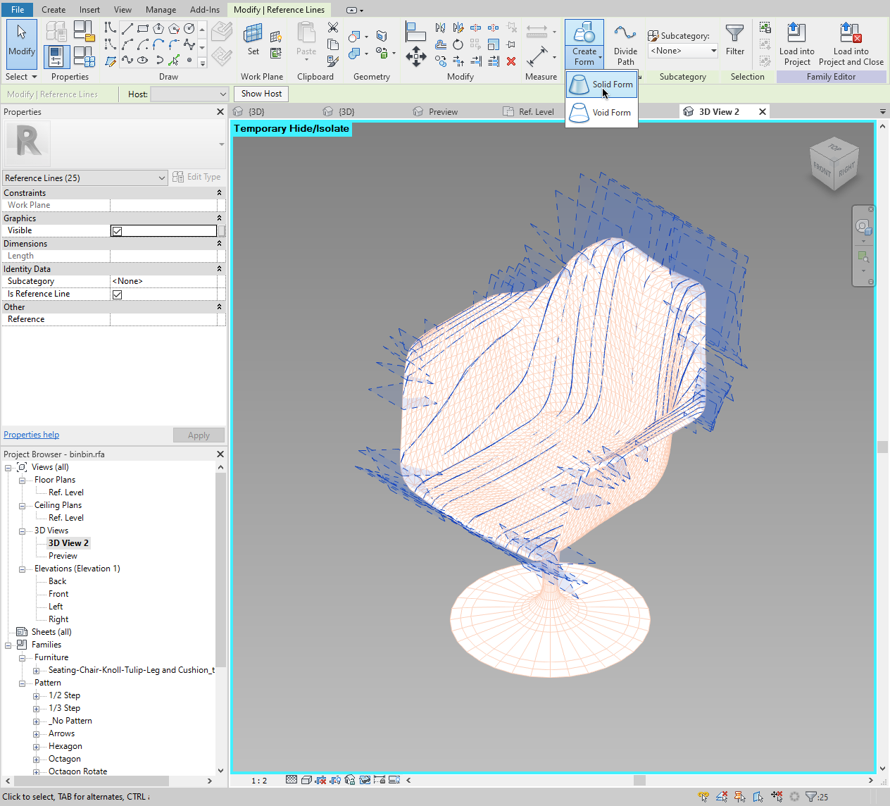
In the screenshots below, the 3D CAD geometry has been inserted into Revit. Let's set the Active Work Plane to "Center Left/Right" and then click "Show".
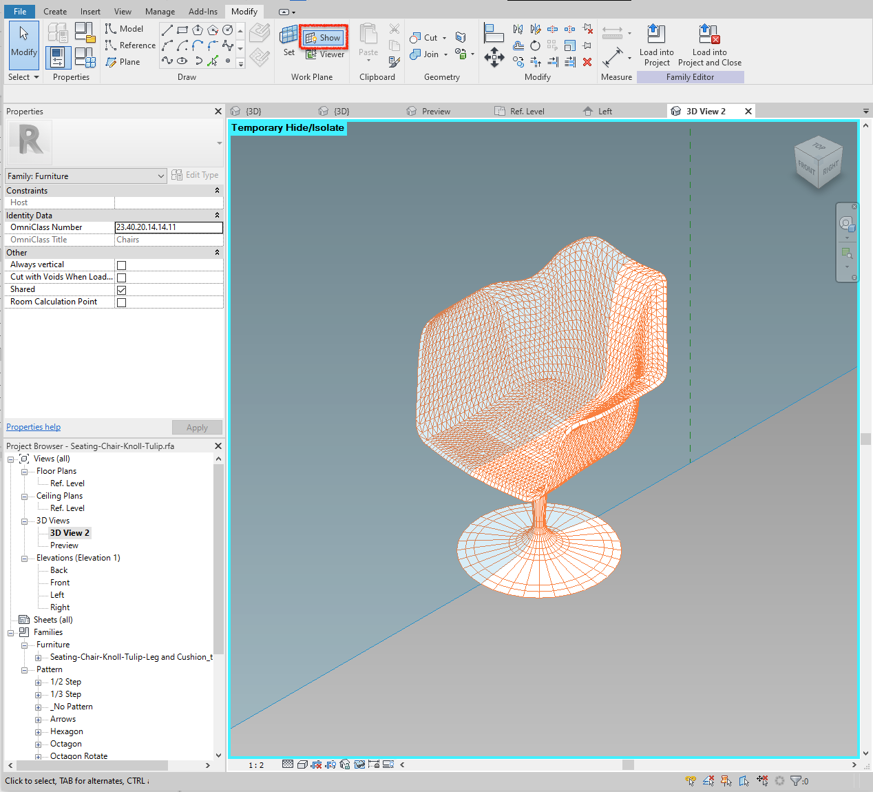
By showing the active plane, we can see where that plane intersects the imported geometry. In effect, we can now trace this intersection with a spline to create a profile. Then we create a new reference plane next to it, make it active, show, trace, rinse and repeat until we get to the edge.
Because our chair is symmetrical, we only need to create profiles either to the left or right of the centre plane. Then we mirror the geometry to the other side.
All profiles can be drawn in Revit's 3D view. Because we are constrained to draw on the (now visible) active plane, as long as we follow the line of intersection, the orientation of the model on the screen doesn't matter. We can orbit and pan as needed.
At this point, the entire workflow turns into a connect-the-dots exercise where we can trace profiles of the 3D CAD model, staying true to the manufacturer's information. Ideally, this should remove a lot of guesswork and only require minimal tweaking in the end.
Below is the complete step-by-step guide to the workflow in Revit, followed by a few tips and notes.
Step-by-Step Guide
- Start a new Revit family using the Generic Model Adaptive Template.
2. Link your reference 3D CAD geometry using default settings. Make sure to delete and purge it at the end!
3. In 3D view, make the Center Left/Right plane active.

4. Show the active plane.

5. Draw one continuous spline, roughly following the intersection until the end of the slice.
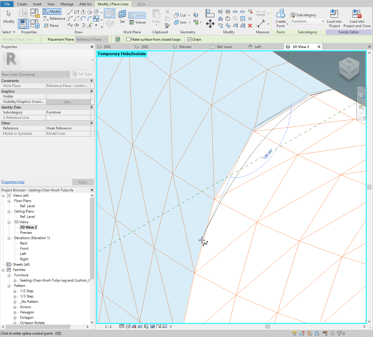
6. Using the spline's control vertices, adjust the spline so that the line follows the intersection as closely as possible. Add or remove control points as needed – the fewer the better.
7. With the first profile complete, go to the plan view and draw another reference plane to the left of center.
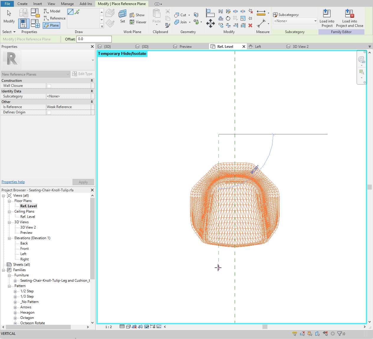
8. Return to 3D View, set the newly created reference plane as active and click "show" (see steps 3 and 4 above).
9. Rinse and repeat until you reach the edge. When all profiles on one side are created as below, mirror them about the Center Left/Right plane.
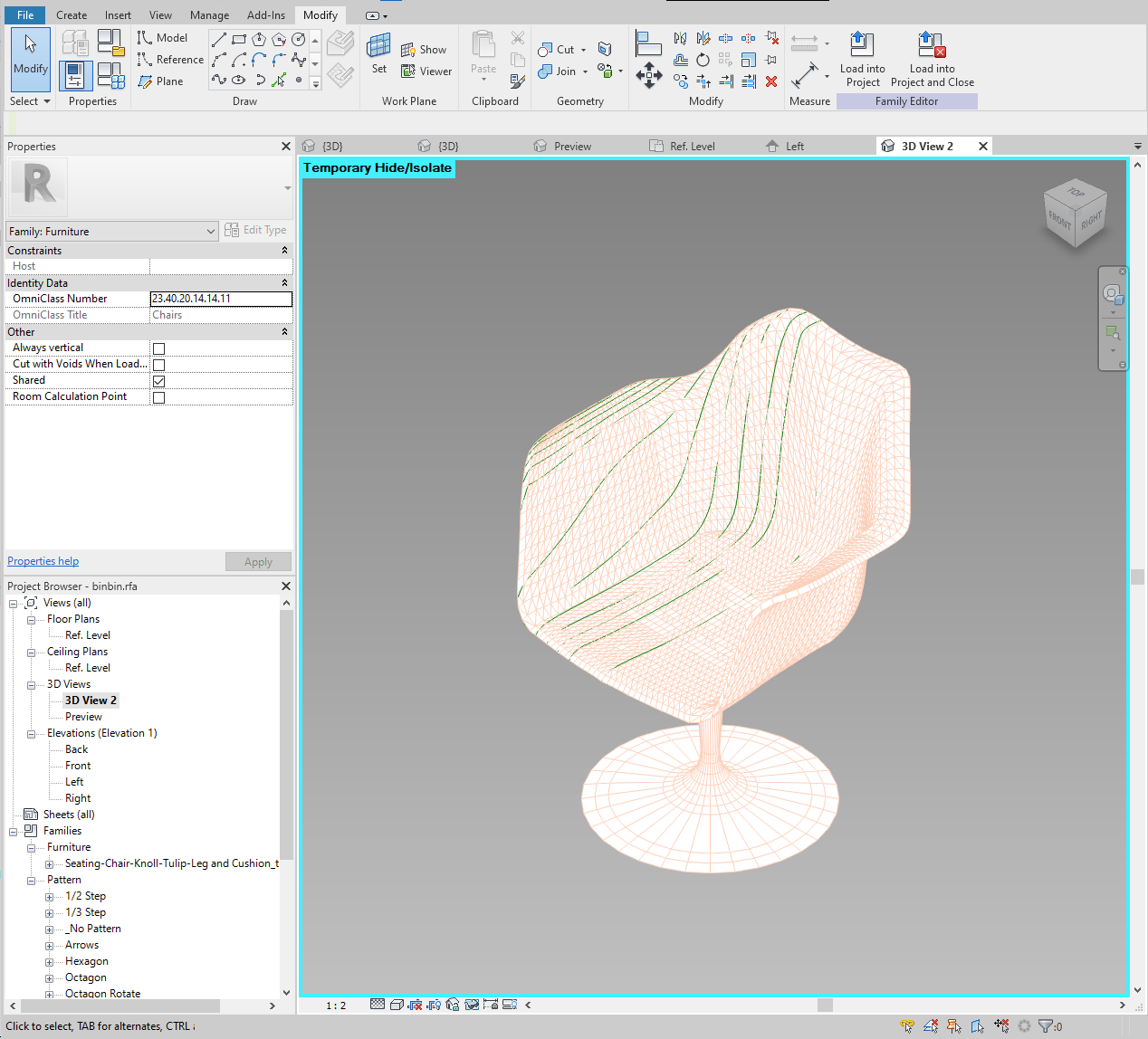
10. Finally, select all splines and create the form. You're done!
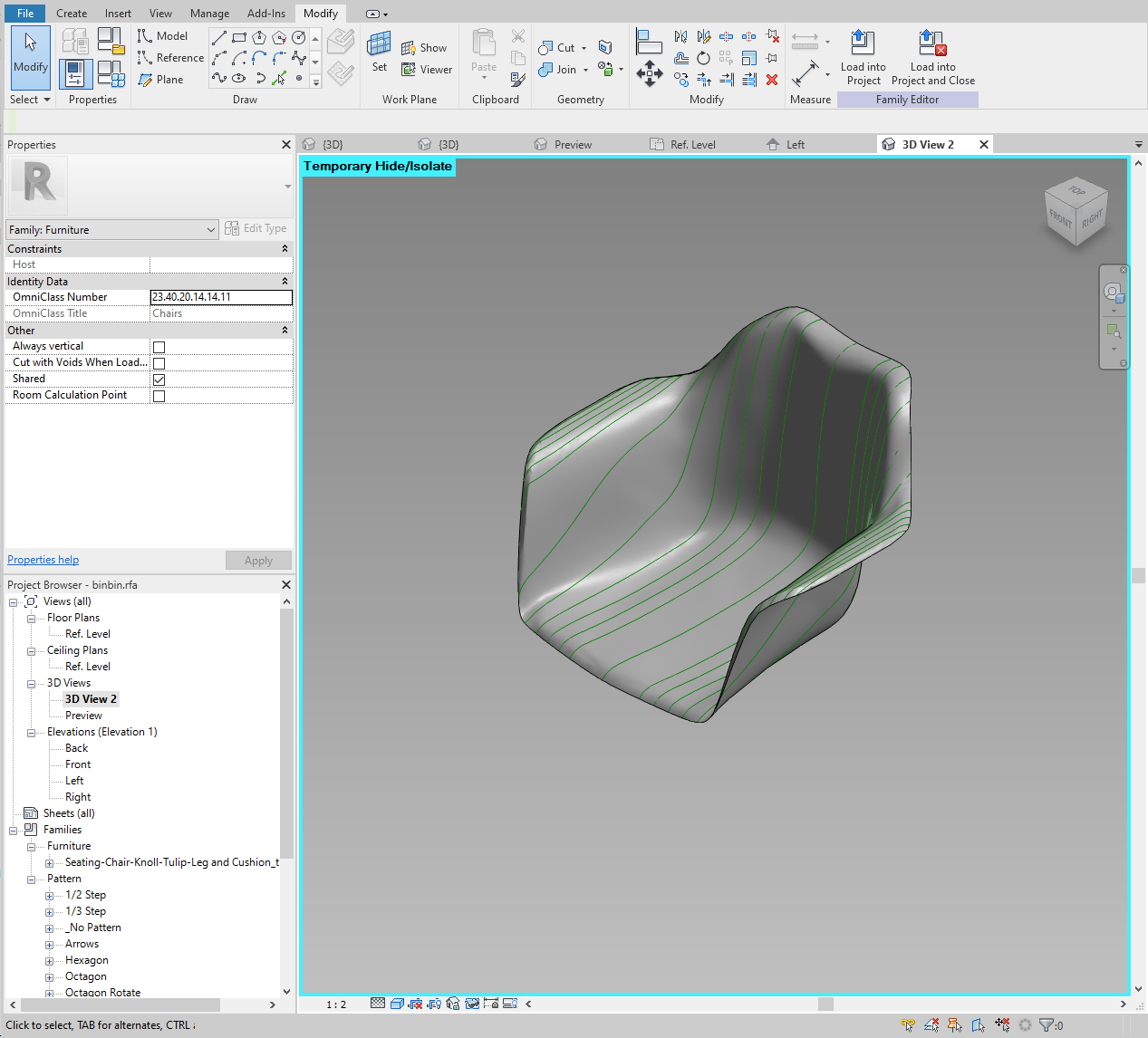
The Result
We end up with the shell weighing a healthy 830 KB, and the combined Revit family totaling 1.07 MB with the nested leg (430 KB). If this was a regular component family, this would be on the hefty side. However, we've nested a leg which comes at a cost anyway, and, more importantly, we have a render-worthy family.
The Revit family overall is less complex and is significantly smaller than the best attempt at doing it using conventional solids and voids.
And here's the kicker: it's all native Revit geometry.
Another thing worth mentioning is flexibility and, consequently, parameters pertaining to the geometry. In contrast to something like a table, which could support multiple or arbitrary sizes, a Revit family like this is not designed to be flexed for different types or instances.
So it's ok to keep the family simple. General dimensions such as length, width and height, as well as seat height and maybe seat depth, will give all relevant information needed for coordination. This, however, is a story for another blog post.
Tips and Notes
1. The fewer profiles the better. The Revit family will be lighter and dense profiles can create issues when trying to create a form.
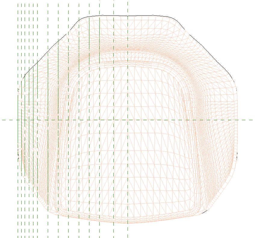
2. Towards the center, where the difference between adjacent profiles is small, profiles should be sparse. Profiles should increase in density towards the edge of the chair. See sample image below.
3. Test each new profile along the way to ensure there are no issues with creating the form. After each profile is drawn, try creating a form using the new and existing lines. If it breaks, it is likely that the profiles are too close together or the bends in the profile are too tight.
4. Any changes to profiles are best done on one side only (i.e. either left or right). Then, when adjustments are complete: delete the form, delete the lines on the unedited side, mirror the edited lines and create the form. It is much faster and easier than trying to adjust the pair of profiles to match.
5. Start and End points of the profile spline should snap to the CAD geometry. For all the points in between, it's best to turn snaps off completely (default shortcut "SO") during fine adjustments. Spline's control points (other than start and end) do not necessarily need to fall on the line itself.