Clearance Zones in Revit
Improve your design, coordination and clash detection with our recommended workflow for incorporating clearance zones into your Revit families.
Clearance Zones in Revit
Improve your design, coordination and clash detection with our recommended workflow for incorporating clearance zones into your Revit families.

Modeling clearance zones in Revit brings key benefits for design, coordination and clash detection. Here we share our recommended workflow for incorporating them into your Revit families.
Many pieces of equipment require clear and unobstructed space around them.
Whether that space is needed for maintenance or installation access, ADA or DDA requirements or to enable airflow, it’s helpful to include this information in a Revit family by specifying clearance zones.
Clearance zones help designers make informed decisions when setting out the space required, and offer a way for MEP coordinators to ensure sufficient access around equipment to help avoid nasty surprises on site. You can also include clearance zones in clash detection, which can highlight coordination issues that would otherwise go unnoticed.
So, how do we set this up in Revit?

An unofficial workflow
Unfortunately, clearance zones are not a concept or feature in Revit, so we are forced to mock them up using family geometry. Without a clear definition to work with, the community has over time come to a consensus on a few points:
Place clearance zones within their own subcategory.
Use a semi-transparent material, such as glass, for the 3D geometry, and use this same material for all clearance zones in the project.
Add a visibility parameter to the related 3D and 2D geometry to allow users to show or hide clearance zones for individual instances in the model.
The aim is to have one material in a model that represents the clearance zone. For each Revit category, a sub-category will hold all of the related geometry and detailing.
In practice, however, each firm and content creator has their own idea of how to name clearance zones and what they should look like. A typical project will contain materials such as “Clearances”, “Clearance Zone”, “clearance zones”, “Access Space”, “ADA_Allowance”, etc. Sub-category listings look fairly similar and are equally fun to work with.
You should definitely check out Jose Fandos’s post: ”Clearances in Revit: Worthy of Their Own Subcategory?” on the success (or maybe the lack thereof) of the above approach. But one thing is clear: until Revit manages clearance zones out-of-the-box itself, it is up to us to apply the standard to the subcategories and materials across all families that we use in our models.
Accidental selection
In addition to the free-for-all in naming standards and the lack of an easy way to manage clearance zones at the model level, there is one other bump to overcome.
Due to the way Revit handles invisible geometry, it’s possible to accidentally select a family in the model without the cursor ever coming close to it. This is because reference planes of the family in a model extend all the way to the edge of the bounding box around that family – regardless of whether an element within that family is visible or not.
This means that despite the clearance zone category and/or visibility parameter being turned off for the geometry, reference planes still extend as if it was there! In effect, this means we have a family that can be unintentionally selected, aligned or dimensioned to.
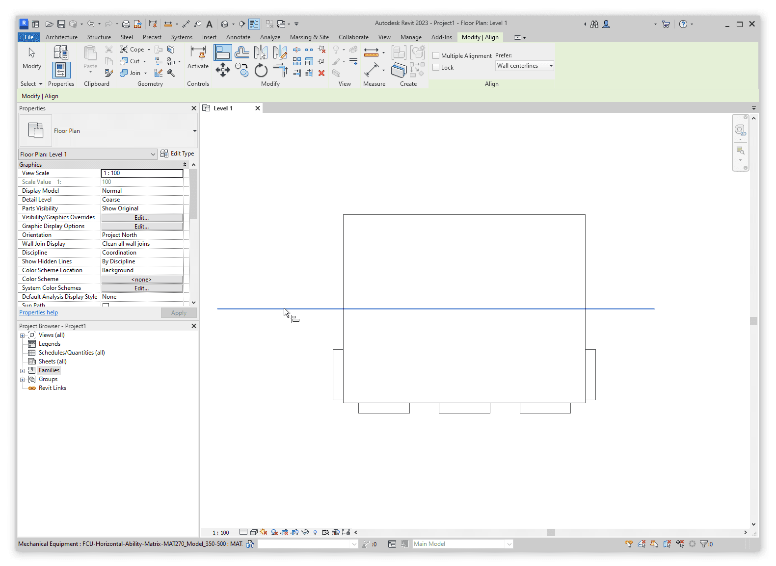
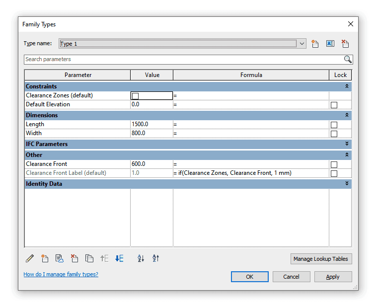
To prevent this, when clearance zones are turned off they need to shrink. Whilst there is not much we can do when the clearance zones are turned off or filtered out en-masse, the clearance visibility parameter in a family can be used to control the zone's dimensions. When enabled, it extends the geometry to create a specified clearance zone; when disabled, the zone retracts.
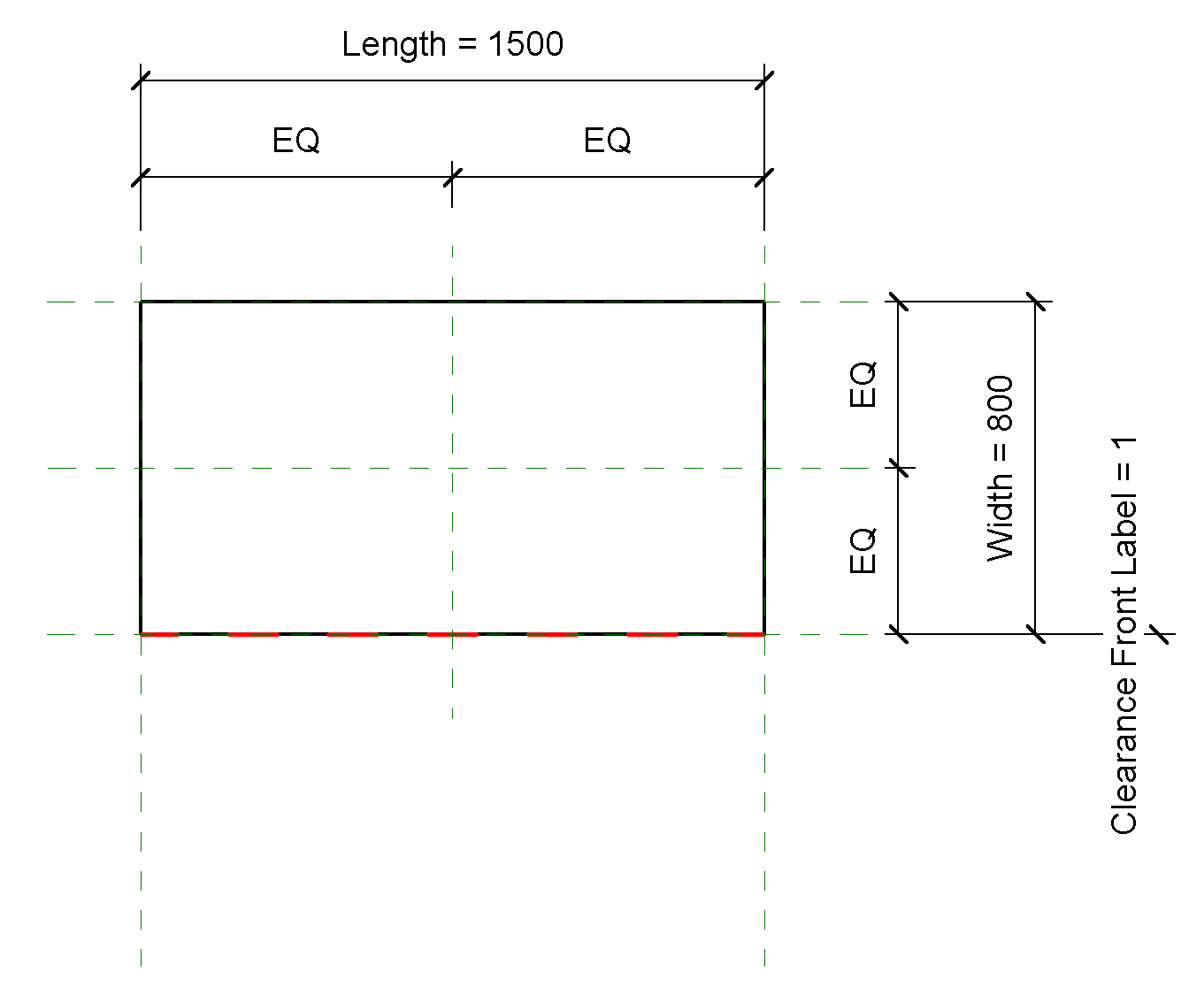
In effect, with the clearance turned off, reference planes no longer extend far enough to be a problem. It’s not necessary to shrink the zone down to zero. In the example below where the clearance zone is at the front, we can set the dimension to 1mm when the zones are disabled to allow for minimum extrusion thickness and any detailing that may be there.
Sure, with some work we can make the zone hide within the family completely, but it’s not worth making the family more complicated to do so. The extension of 1 mm is not noticeable in the project and there is no benefit in fixing it.

Now, as when assigning instance parameters to dimensions, grips may show up when that family is loaded into a model. But fear not! If you want some help getting to grips with... grips, be sure to check out our other post: “Getting to Grips with Revit Family Grips”.
Make do and build
Even with the above method, clearance zones remain a pain to deal with.
On the one hand, it would be nice to be able to manage clearance zones on a per-view basis. For example, hiding them in documentation views, but keeping them visible in working views or 3D views intended for export for clash detection. On the other hand, to avoid having families that can be unintentionally selected, we are forced to manage each family individually by shrinking its clearance zone as well as hiding the geometry.
Ideally “Clearance Zones” would be a built-in subcategory, and they would not contribute to the hitbox of the family when selecting (similar to how the Light Source category behaves when hidden in the view). But until the concept of clearance zones gets added to Revit, we need to deal with the complications of using actual family geometry to represent them. In our experience, if you find a good workflow for clearance zones, the added effort is worth the benefits they bring for design, coordination and clash detection.
Modeling clearance zones in Revit brings key benefits for design, coordination and clash detection. Here we share our recommended workflow for incorporating them into your Revit families.
Many pieces of equipment require clear and unobstructed space around them.
Whether that space is needed for maintenance or installation access, ADA or DDA requirements or to enable airflow, it’s helpful to include this information in a Revit family by specifying clearance zones.
Clearance zones help designers make informed decisions when setting out the space required, and offer a way for MEP coordinators to ensure sufficient access around equipment to help avoid nasty surprises on site. You can also include clearance zones in clash detection, which can highlight coordination issues that would otherwise go unnoticed.
So, how do we set this up in Revit?
An unofficial workflow
Unfortunately, clearance zones are not a concept or feature in Revit, so we are forced to mock them up using family geometry. Without a clear definition to work with, the community has over time come to a consensus on a few points:
Place clearance zones within their own subcategory.
Use a semi-transparent material, such as glass, for the 3D geometry, and use this same material for all clearance zones in the project.
Add a visibility parameter to the related 3D and 2D geometry to allow users to show or hide clearance zones for individual instances in the model.
The aim is to have one material in a model that represents the clearance zone. For each Revit category, a sub-category will hold all of the related geometry and detailing.
In practice, however, each firm and content creator has their own idea of how to name clearance zones and what they should look like. A typical project will contain materials such as “Clearances”, “Clearance Zone”, “clearance zones”, “Access Space”, “ADA_Allowance”, etc. Sub-category listings look fairly similar and are equally fun to work with.
You should definitely check out Jose Fandos’s post: ”Clearances in Revit: Worthy of Their Own Subcategory?” on the success (or maybe the lack thereof) of the above approach. But one thing is clear: until Revit manages clearance zones out-of-the-box itself, it is up to us to apply the standard to the subcategories and materials across all families that we use in our models.
Accidental selection
In addition to the free-for-all in naming standards and the lack of an easy way to manage clearance zones at the model level, there is one other bump to overcome.
Due to the way Revit handles invisible geometry, it’s possible to accidentally select a family in the model without the cursor ever coming close to it. This is because reference planes of the family in a model extend all the way to the edge of the bounding box around that family – regardless of whether an element within that family is visible or not.
This means that despite the clearance zone category and/or visibility parameter being turned off for the geometry, reference planes still extend as if it was there! In effect, this means we have a family that can be unintentionally selected, aligned or dimensioned to.
To prevent this, when clearance zones are turned off they need to shrink. Whilst there is not much we can do when the clearance zones are turned off or filtered out en-masse, the clearance visibility parameter in a family can be used to control the zone's dimensions. When enabled, it extends the geometry to create a specified clearance zone; when disabled, the zone retracts.
In effect, with the clearance turned off, reference planes no longer extend far enough to be a problem. It’s not necessary to shrink the zone down to zero. In the example below where the clearance zone is at the front, we can set the dimension to 1mm when the zones are disabled to allow for minimum extrusion thickness and any detailing that may be there.
Sure, with some work we can make the zone hide within the family completely, but it’s not worth making the family more complicated to do so. The extension of 1 mm is not noticeable in the project and there is no benefit in fixing it.
Now, as when assigning instance parameters to dimensions, grips may show up when that family is loaded into a model. But fear not! If you want some help getting to grips with... grips, be sure to check out our other post: “Getting to Grips with Revit Family Grips”.
Make do and build
Even with the above method, clearance zones remain a pain to deal with.
On the one hand, it would be nice to be able to manage clearance zones on a per-view basis. For example, hiding them in documentation views, but keeping them visible in working views or 3D views intended for export for clash detection. On the other hand, to avoid having families that can be unintentionally selected, we are forced to manage each family individually by shrinking its clearance zone as well as hiding the geometry.
Ideally “Clearance Zones” would be a built-in subcategory, and they would not contribute to the hitbox of the family when selecting (similar to how the Light Source category behaves when hidden in the view). But until the concept of clearance zones gets added to Revit, we need to deal with the complications of using actual family geometry to represent them. In our experience, if you find a good workflow for clearance zones, the added effort is worth the benefits they bring for design, coordination and clash detection.


Kinship
The best way to manage Revit content
Kinship
The best way to manage Revit content
Kinship
The best way to manage Revit content
Similar Articles


Never miss an update with our monthly newsletter
Get the latest company news, product updates, blog posts and free Revit content from Kinship. Delivered directly to your inbox no more than once a month.
By submitting your email, you agree to receive newsletter emails.
Support
Never miss an update with our monthly newsletter
Get the latest company news, product updates, blog posts and free Revit content from Kinship. Delivered directly to your inbox no more than once a month.
By submitting your email, you agree to receive newsletter emails.
Support
Never miss an update with our monthly newsletter
Get the latest company news, product updates, blog posts and free Revit content from Kinship. Delivered directly to your inbox no more than once a month.
By submitting your email, you agree to receive newsletter emails.
Support